Visio 2010 Uml Sequence Diagram Loop
To build a sequence diagram, use a UML Sequence template or starter diagram, which includes the UML Sequence stencil. Drag shapes from the stencil onto the drawing canvas to build the diagram.
Start a sequence diagram
-
Start Visio. Or if you have a file open already, click File > New.
-
In the Search box, type UML sequence.
-
Select the UML Sequence diagram.
-
In the dialog box, select the blank template or one of the three starter diagrams. (A description of each one is shown on the right when you select it.) Then select either Metric Units or US Units.
-
Select Create.
-
The diagram opens. You should see the Shapes window next to the diagram. If you don't see it, go to View > Task Panes and make sure that Shapes is selected. If you still don't see it, click the Expand the Shapes window button on the left.
-
On the View tab, make sure the check box next to Connection Points is selected. This option makes connection points appear when you start connecting shapes.
-
Now, drag shapes you want to include in your diagram from the Shapes window to the page. To rename text labels, double-click the labels.
Lifelines for actors and objects
Use an Actor lifeline shape for each participant, and an Object lifeline shape for each system component in your process.
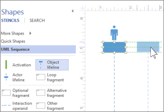
Tip:As you drag the lifelines into place, green alignment guides appear onscreen to help you line up and space the lifelines relative to the other lifeline shapes.
-
Double-click in the heading box for each lifeline to enter a name or title.
-
To lengthen or shorten a timeline, click the lifeline, then drag the yellow control point at the bottom of the lifeline.
Messages
Use message shapes to represent information being sent between lifelines.
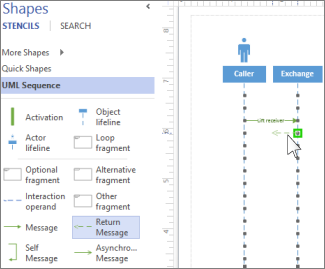
Tip: Visio helps you glue the message endpoints to each lifeline. A green circle appears at the endpoint when it glues to a connection point. The connections points disappear when you are done dragging.
-
Attach the beginning endpoint to the lifeline sending the message, then drag the head endpoint to the lifeline receiving the message.
-
Double-click the message shape to create a text box, and type a name for the message.
-
Use a Message shape (a solid line) to represent a request or the transmitting of information.
-
Use a Return Message shape (a dashed line) to represent a response to a prior message.
-
Use a Self Message to represent a recursive call of an operation, or one method calling another method belonging to the same object.
-
Use the Asynchronous Message shape to show when an action might not happen immediately.
-
To change the shape of a connector message:
-
Right-click the connector.
-
At the bottom of the pop-up menu, select from the three options (Right-Angle, Straight, Curved).
-
Click and drag the connector to change its shape.
-
Fragments
If one or more interactions form a loop, or require a condition to be met to end the interaction, enclose those interactions in a fragment shape:
-
Use the Loop fragment for a basic repeating interaction.
-
Use the Optional fragment for steps that are only performed if a certain condition is met.
-
Use the Alternative fragment shape for an if-then or if-then-else process or interaction. The fragment comes with two sections, which let you show the alternative interaction. To add another condition, drag an Interaction operand onto the shape.

-
Drag the fragment shape to the interactions it relates to. Use the sizing handles on the fragment shape to ensure it encloses all of the related interactions.
-
Double-click in the title corner of the fragment shape to add a title or short description of the process enclosed by the fragment. Below the title corner, click the [parameters] prompt if you want to enter the conditions that would end that process.
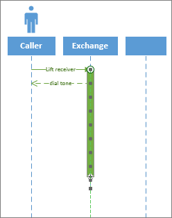
Activation
Place an Activation bar shape on a lifeline to show when and for how long that object or participant is active in the process. Typically, there will be arrows going to and from an activation box to demonstrate the flow of information.
Drag the endpoints of the Activation bar up or down to make it the length that you want.
Destruction
Destruction indicates when an object or actor is done participating in a system. A large X appears at the end of its lifeline. To show destruction of an object in a diagram:
-
Right-click the object, and select Show Destruction.
To build a sequence diagram, use a UML Sequence template or starter diagram, which includes the UML Sequence stencil. Drag shapes from the stencil onto the drawing canvas to build the diagram.
Start a sequence diagram
-
Open Visio for the web.
-
Near the upper right corner of the page, select More templates.
-
In the Gallery, scroll down to the UML Sequence row.
The first item in the row represents a blank template plus the companion stencil. The other items in the row are sample diagrams that have some shapes already drawn to help you get started quickly.
-
Click any item to see a larger preview.
-
When you find the diagram you want to use, click its Create button.
The new diagram, with the related stencil, opens in your browser.
Lifelines for actors and objects
Use an Actor lifeline shape for each participant, and an Object lifeline shape for each system component in your process.
Tip:As you drag the lifelines into place, green alignment guides appear onscreen to help you line up and space the lifelines relative to the other lifeline shapes.
-
Double-click in the heading box for each lifeline to enter a name or title.
-
To lengthen or shorten a timeline, click the lifeline, then drag the yellow control point at the bottom of the lifeline.
Messages
Use message shapes to represent information being sent between lifelines.
Tip: Visio helps you glue the message endpoints to each lifeline. A green circle appears at the endpoint when it glues to a connection point. The connections points disappear when you are done dragging.
-
Attach the beginning endpoint to the lifeline sending the message, then drag the head endpoint to the lifeline receiving the message.
-
Double-click the message shape to create a text box, and type a name for the message.
-
Use a Message shape (a solid line) to represent a request or the transmitting of information.
-
Use a Return Message shape (a dashed line) to represent a response to a prior message.
-
Use a Self Message to represent a recursive call of an operation, or one method calling another method belonging to the same object.
-
Use the Asynchronous Message shape to show when an action might not happen immediately.
-
To change the shape of a connector message:
-
Right-click the connector.
-
At the bottom of the pop-up menu, select from the three options (Right-Angle, Straight, Curved).
-
Click and drag the connector to change its shape.
-
Fragments
If one or more interactions form a loop, or require a condition to be met to end the interaction, enclose those interactions in a fragment shape:
-
Use the Loop fragment for a basic repeating interaction.
-
Use the Optional fragment for steps that are only performed if a certain condition is met.
-
Use the Alternative fragment shape for an if-then or if-then-else process or interaction. The fragment comes with two sections, which let you show the alternative interaction. To add another condition, drag an Interaction operand onto the shape.
-
Drag the fragment shape to the interactions it relates to. Use the sizing handles on the fragment shape to ensure it encloses all of the related interactions.
-
Double-click in the title corner of the fragment shape to add a title or short description of the process enclosed by the fragment. Below the title corner, click the [parameters] prompt if you want to enter the conditions that would end that process.
Activation
Place an Activation bar shape on a lifeline to show when and for how long that object or participant is active in the process. Typically, there will be arrows going to and from an activation box to demonstrate the flow of information.
Drag the endpoints of the Activation bar up or down to make it the length that you want.
Destruction
Destruction indicates when an object or actor is done participating in a system. A large X appears at the end of its lifeline. To show destruction of an object in a diagram:
-
Right-click the object, and select Show Destruction.
To build a sequence diagram, use the UML Model template, which includes a set of UML Sequence shapes. Drag shapes from the stencil onto the drawing canvas to build the diagram.
Start a sequence diagram
-
Under Template Categories, click Software and Database, and then click UML Model Diagram.
-
In the Model Explorer tree view, right-click the package in which you want to include the static structure diagram, point to New, and click Sequence Diagram.
A blank page appears, and the UML Sequence stencil becomes the top-most stencil. An icon representing the diagram is added to the tree view.
Note:If the tree view isn't visible, point to View on the UML menu, and then click Model Explorer.
Read on for more guidance about working with sequence diagrams.
Lifelines for actors and objects
Use an Object lifeline shape for each participant and system component in your process.
An object lifeline represents the existence of an object at a particular time. If the object is created or destroyed during the time period the diagram represents, the lifeline stops or starts at the appropriate point. An object's destruction is marked with a large X.
Use a Lifeline shape  to show conditionality on an object lifeline.
Messages
-
Drag a Message shape onto the drawing page.
The message shape you choose depends upon the kind of message you want to send (regular, asynchronous, procedure call, or return).
-
Glue the message endpoint without the arrowhead to a connection point
 on the lifeline of the object sending the message.
 -
Glue the message endpoint with the arrowhead to a connection point on the lifeline of the object receiving the message.
-
Double-click the message, and then type or choose the message name, stereotype, sequence expression, and flow kind.
-
For a flat message or procedure call, choose the operation you want the message to generate. If the operation doesn't exist, click New to create it.
For an asynchronous message, choose the signal you want the message to generate. If no reception for the signal exists on the classifier that the object lifeline receiving the message is based on, click New to create the reception.
Tip:To indicate a message from an object to itself, glue the two endpoints on an arc-shaped Message shape to two connection points on the same object lifeline.
Constraints
If one or more interactions require a condition to be met to end the interaction, enclose those interactions in one of the constraint shapes:
-
A Constraint
 is a specification for conditions and propositions that must be maintained as true for the system to be valid. Constraints are expressed as text within braces ({ }) and may be written in a predefined language, such as Object Constraint Language (OCL) or in natural language.
Drag the control handle
 at the center of the Constraint shape and glue it to a connection point on another element.
 -
A 2-element Constraint
 applies to two elements, such as two classes or two associations. The constraint is shown as a dashed arrow from one element to the other with the constraint string label in braces ({ }).
 -
An OR Constraint
 indicates that any instance of a class may participate in only one association at one time. The constraint is shown as a dashed line connecting two or more associations, which must have a class in common. The line is labeled by the constraint string, OR, in braces ({ }).
Activation
Place an Activation bar shape on a lifeline to show when and for how long that object or participant is active in the process. Typically, there will be arrows going to and from an activation box to demonstrate the flow of information.
Drag the endpoints of the Activation bar up or down to make it the length that you want.
Destruction
Destruction indicates when an object or actor is done participating in a system. A large X appears at the end of its lifeline. To show destruction of an object in a diagram:
-
Right-click the object, select Shape Display Options, and in the dialog box, select the Destruction marker box.
Source: https://support.microsoft.com/en-us/office/create-a-uml-sequence-diagram-c61c371b-b150-4958-b128-902000133b26